
If you stop its a reverse flow of any voltage current, then i have two capacitors over here. So these are two inputs either i can use these cell connectors or i can use this dc jack for the input. This is uh still connectors, so you can use any um block input that are the pc blocks that are attached on the pcb ive, also given a dc jack to my input source. So actually, this atmega328p has a range uh of working from till 5.5 volts, so it works on five volt, so i have made this voltage supply to give it five both. So if i show you in a zoomed manner, lets vote this supply for my uh uno.
Logiciels Librairies for Proteus Sonelec Musique. 150 Watt Amplifier Circuit An Authentic Resource on. Interfacing Seven Segment Displays eXtreme Electronics. Users of ARES, or indeed other PCB software will find some of the.with Electronics.
Below is the implementation for the 1hz frequency generator on proteus.So this is the working of the whole supply, then well move on to the main circuit, so our main circuit contains uh arduino um, that is uh chip, that is at mega three to eight p, so uh this chip contains um one led um. EPanorama net Links.7 segment display. How to add Arduino Library in to Proteus 7 amp 8. Heart rate measurement from fingertip Embedded Lab.
So i have this connected steel connector over here. So i have given this five volt over here so and here i i will connect uh a switch so uh, so you should push button. So next we have a reset button, so this reset works on five volts. The other ports are for the silk connectors that we can use it to connect any other things. This p5 is actually the pin 13 on arduino uno. It is default, pin 13 and which already blinks so hey.
Proteus 7 Segment Pcb Drivers On A
If i give it 0 volt, it will give 5 volt over here and reset it.A Mechanical 7-Segment Display PCB Inspired by Carl Bugejas work, this display uses seven coils and H-bridge drivers on a PCB to actuate each section. If i give 5 volt, it will give 0 over here. So, as you can see this inverse symbol, this reset will inverse.
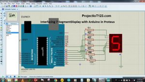
Although this ic can measure a maximum of 15 volts directly, we use voltage divider circuit to lower the input voltage.So we are giving actually 5 volt all the time so that it is not working. The output shown on 3 seven segment displays are nearly 25 volts 25.9 volts. This Proteus simulation diagram clearly depicts that the input voltage is 25 volts.
I am using 16 way house in this that, like the or you know, uno um board uses. Um knows its speed of working uh at mega 328p has a maximum uh of 20 megahertz uh of crystal can be used with it. So what is crystal the crystal? Provides the clock signals uh to this atmega. These are for the crystal input ports. Here you can see – is x, tal1 xtl2.
That is through hole and there i have silk connectors attached to it, and this is the power push button and this capacitor attached ive used in such a way that if i want to use this capacitor, then i can for the safety, and i cannot also so This is up to choice.If you want to use it or not, so there is the led, and this resistor for the led is the 22 ohm resistor and that is attached to pb 5, and this is a 10k resistor that is attached to the reset button, and this is this is Reset pin one – and this is a vcc on the other end, so this whole side is our voltage supply. That is a dip connection chip. You can see this atmega328p chip. So here you can see the pcb layout for the circuit. So this is a crystal circuit, so, as we have been done with this um schematic next, we will move on to our pcb layout. That is a non polar capacitor and do buffer of crystal over here.
That indicates our uh circuit is working on uh thats. Then we have to have two capacitor more and then the led and a resistor of 22 ohms. That is a 5 volt voltage regulator. So i have just ignored it because my connections are right and this is our silk connectors and then we have a diode and we have two capacitors over here: a voltage regulator of 5 volt 7805.
This is a 3d view of our board, so now we will move on to the hardware implementation of this old circuit. This capacitor voltage regulator, two leds im using uh, so this is our crystal with two peak of our reduced capacitors and as a safety capacitor, and this is the blink led.So you can see the routing if i correct it, see the routing over here and Music. So this is our ac jack are two steel, connectors and um. Then we will move on to 3d visualizer, so here you can see that in uh 3d visualizer how our circuit board will look like.
हिन्दी हिंदी /hi/how-to-make-your-own-arduino-uno-at-home-by-using-proteus.html Ελληνικά /el/how-to-make-your-own-arduino-uno-at-home-by-using-proteus.html Français /fr/how-to-make-your-own-arduino-uno-at-home-by-using-proteus.html Nederlands /nl/how-to-make-your-own-arduino-uno-at-home-by-using-proteus.html Čeština /cs/how-to-make-your-own-arduino-uno-at-home-by-using-proteus.html 粤语 /yue/how-to-make-your-own-arduino-uno-at-home-by-using-proteus.html
Русский /ru/how-to-make-your-own-arduino-uno-at-home-by-using-proteus.html Română /ro/how-to-make-your-own-arduino-uno-at-home-by-using-proteus.html Português /pt/how-to-make-your-own-arduino-uno-at-home-by-using-proteus.html Polski /pl/how-to-make-your-own-arduino-uno-at-home-by-using-proteus.html Latīna /la/how-to-make-your-own-arduino-uno-at-home-by-using-proteus.html


 0 kommentar(er)
